Element Library
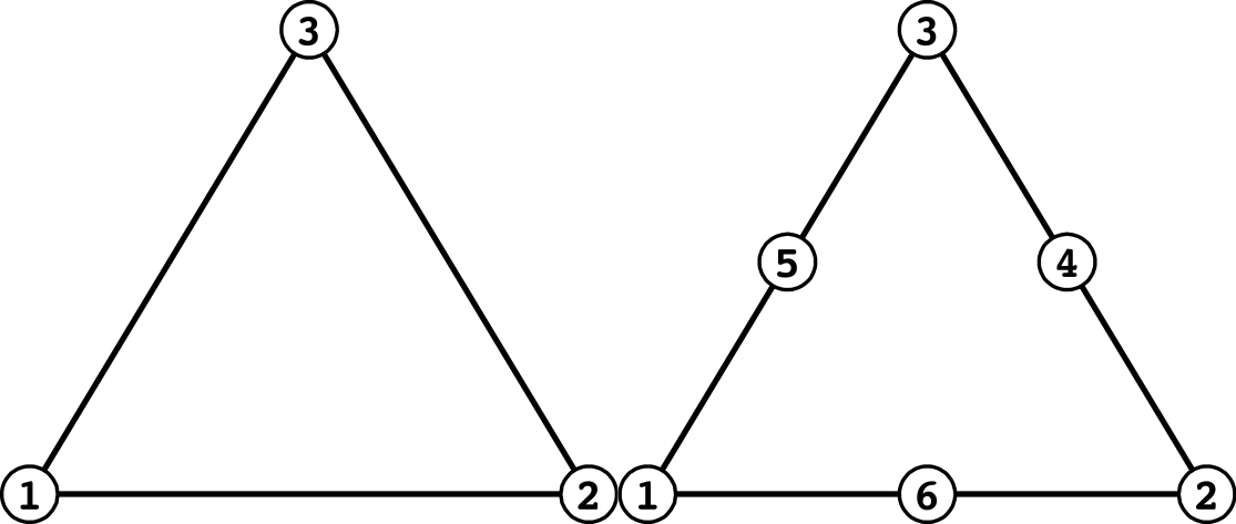
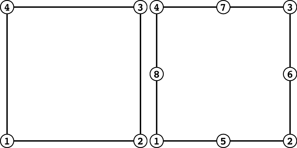
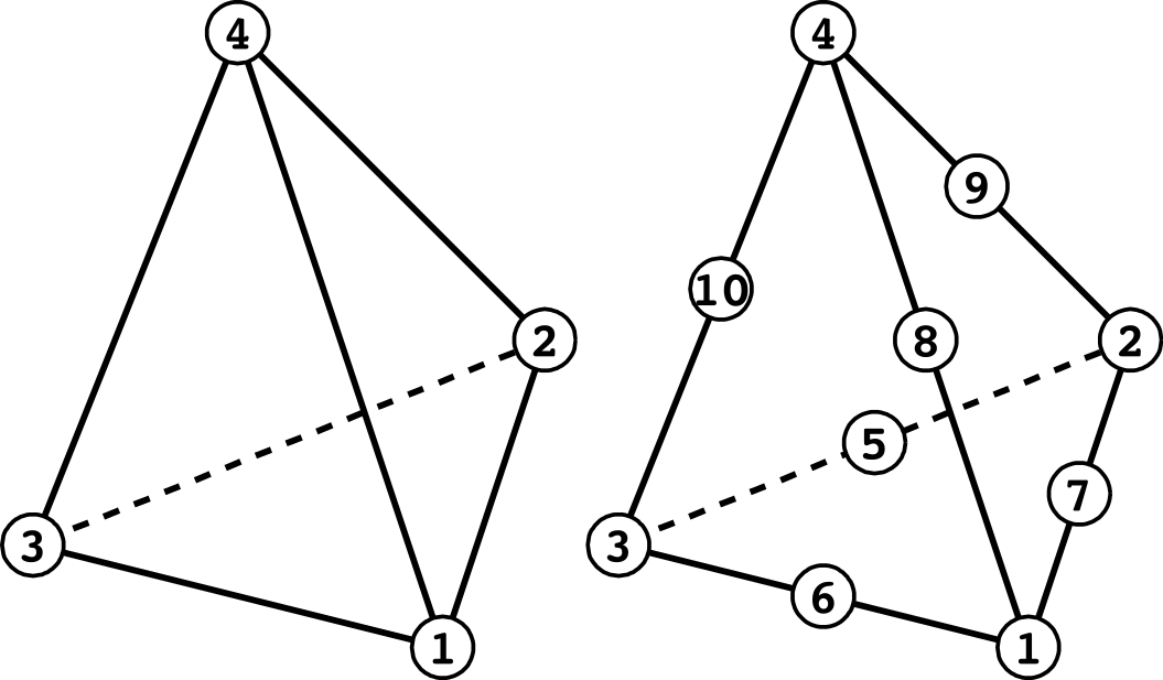
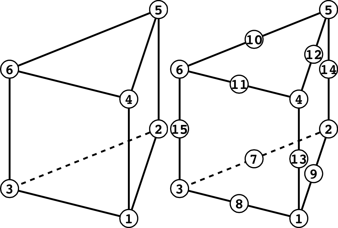
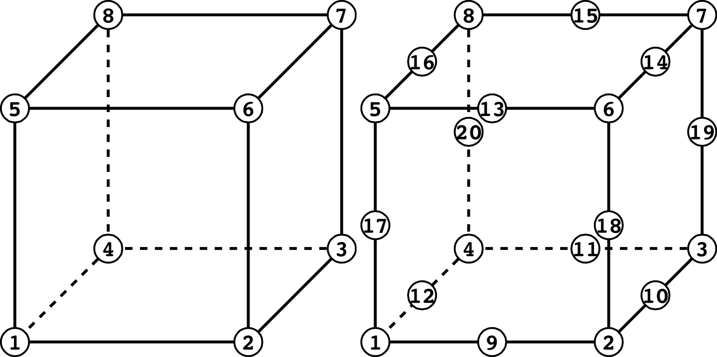
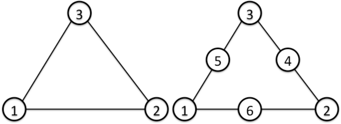
In FrontISTR, the element groups shows in Table 4.1.1 can be used for analysis. Since HEC-MW is used to input the mesh data into FrontISTR, the following descriptions of the element library is based on the description of HEC-MW. The element library is shown in Figure 4.1.1, and element connectivity and the definitions of the surface number are shown in Figure 4.1.2.
Table 4.1.1: Element Library List
| Element Types | Element No. | Description |
|---|---|---|
| Line element | 111 | Two node link element |
| 112 | Three node link element | |
| Plane element | 231 | Three node triangular element |
| 232 | Six node triangular quadratic element | |
| 241 | Four node quadrilateral element | |
| 242 | Eight node quadrilateral quadratic element | |
| Solid element | 301 | Two node truss element |
| 341 | Four node tetrahedral element | |
| 342 | Ten node tetrahedral quadratic element | |
| 351 | Six node pentahedral element | |
| 352 | Fifteen node pentahedral quadratic element | |
| 361 | Eight node hexahedral element | |
| 362 | Twenty node hexahedral quadratic element | |
| Connector element | 511 | Two node connector element (spring, dashpot) |
| Interface element | 541 | Quadrilateral cross section linear element |
| 542 | Quadrilateral cross section quadratic element | |
| Beam element | 611 | Two node beam element |
| 641 | Two node beam element (with four 3-dof nodes) | |
| Shell element | 731 | Three node three-dimensional linear element |
| 732 | Six node three-dimensional quadratic element | |
| 741 | Four node three-dimensional linear element | |
| 743 | Nine node three-dimensional quadratic element | |
| 761 | Three node three-dimensional linear element (with six 3-dof nodes) | |
| 781 | Four node three-dimensional linear element (with eight 3-dof nodes) |
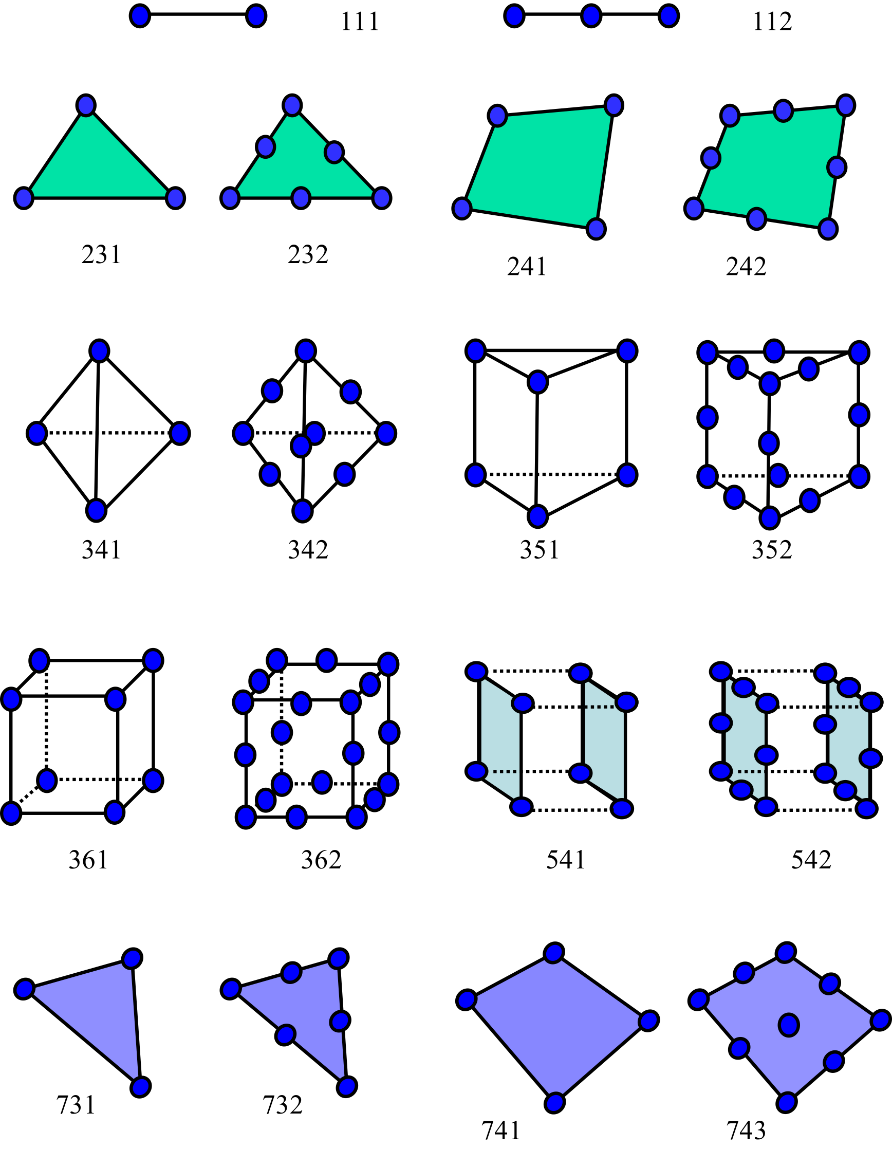
Figure 4.1.1: Element Library
Structural and Plane Elements in Analyses Considering Large Deformation
In an analysis that considers large deformation (geometric nonlinearity), that is, a static or dynamic analysis with NONLINEAR in !SOLUTION (including TYPE=NLSTATIC and TYPE=STATICEIGEN), some beam, shell and plane elements cannot be used or can be used only under a condition. For a model that contains an element that cannot be used, the analysis stops after it starts with the message Element type not supported for nonlinear static analysis.
| Element type | Treatment in an analysis considering large deformation |
|---|---|
| 741 | In nonlinear static analysis, finite rotation is handled when the material is elastic (!ELASTIC). The Total Lagrange formulation is used by default, and specifying CAUCHY in !ELASTIC selects the Updated Lagrange formulation. The Updated Lagrange formulation does not support an orthotropic material or a laminate with an orthotropic layer. In nonlinear dynamic analysis, finite rotation is not supported, and the element can be used only when INFINITESIMAL is specified for the material. |
| 731, 743 | Can be used only when INFINITESIMAL is specified for the material. The element is treated as infinitesimal deformation. |
| 231, 232, 241, 242 | Can be used only when INFINITESIMAL is specified for the material. The element is treated as infinitesimal deformation. |
| 611, 641, 761, 781 | Cannot be used. The analysis stops even when INFINITESIMAL is specified for the material. |
Element 741 is the only shell element that handles finite rotation. To treat a thin-walled structure with large rotation in an analysis that considers large deformation, model it with 741. Beam elements and the elements with 3-dof nodes cannot be used in an analysis that considers large deformation, so represent a beam-like member with solid elements. INFINITESIMAL and CAUCHY are parameters of the material keywords. See !ELASTIC for details.
(Line Element)

(Triangular Plane Element)
| Surface No. | Linear | Quadratic |
|---|---|---|
| 1 | 1 - 2 | 1 - 6 - 2 |
| 2 | 2 - 3 | 2 - 4 - 3 |
| 3 | 3 - 1 | 3 - 5 - 1 |
(Quadrilateral Plane Element)
| Surface No. | Linear | Quadratic |
|---|---|---|
| 1 | 1 - 2 | 1 - 5 - 2 |
| 2 | 2 - 3 | 2 - 6 - 3 |
| 3 | 3 - 4 | 3 - 7 - 4 |
| 4 | 4 - 1 | 4 - 8 - 1 |
(Tetrahedral Element)
| Surface No. | Linear | Quadratic |
|---|---|---|
| 1 | 1 - 2 - 3 | 1 - 7 - 2 - 5 - 3 - 6 |
| 2 | 1 - 2 - 4 | 1 - 7 - 2 - 9 - 4 - 8 |
| 3 | 2 - 3 - 4 | 2 - 5 - 3 - 10 - 4 - 9 |
| 4 | 3 - 1 - 4 | 3 - 6 - 1 - 10 - 4 - 8 |
(Pentahedral Element)
| Surface No. | Linear | Quadratic |
|---|---|---|
| 1 | 1 - 2 - 3 | 1 - 9 - 2 - 7 - 3 - 8 |
| 2 | 4 - 5 - 6 | 4 - 12 - 5 - 10 - 6 - 11 |
| 3 | 1 - 2 - 5 - 4 | 1 - 9 - 2 - 14 - 5 - 12 - 4 - 13 |
| 4 | 2 - 3 - 6 - 5 | 2 - 7 - 3 - 15 - 6 - 10 - 5 - 14 |
| 5 | 3 - 1 - 4 - 6 | 3 - 8 - 1 - 13 - 4 - 11 - 6 - 15 |
(Hexahedral Element)
| Surface No. | Linear | Quadratic |
|---|---|---|
| 1 | 1 - 2 - 3 - 4 | 1 - 9 - 2 - 10 - 3 - 11 - 4 - 12 |
| 2 | 5 - 6 - 7 - 8 | 5 - 13 - 6 - 14 - 7 - 15 - 8 - 16 |
| 3 | 1 - 2 - 6 - 5 | 1 - 9 - 2 - 18 - 6 - 13 - 5 - 17 |
| 4 | 2 - 3 - 7 - 6 | 2 - 10 - 3 - 19 - 7 - 14 - 6 - 18 |
| 5 | 3 - 4 - 8 - 7 | 3 - 11 - 4 - 20 - 8 - 15 - 7 - 19 |
| 6 | 4 - 1 - 5 - 8 | 4 - 12 - 1 - 17 - 5 - 16 - 8 - 20 |
(Connector Element)
To connect two nodes by a discrete spring or dashpot, the 2-node connector element (element type 511) is used. A connector element gives only stiffness or damping between the two nodes it connects; it has no shape, no cross section and no mass.
A connector element can represent four kinds of characteristics, which are determined by the material assigned to the element.
- Axial spring — a spring acting along the axis connecting the two nodes. Its direction follows the deformation of the model. It is given by
!SPRING_A. - Spring with specified degrees of freedom — a spring connecting a specified degree of freedom of one node with a specified degree of freedom of the other node. Its direction is determined by the degree-of-freedom numbers and does not follow the deformation. A different spring constant can be given for each direction. It is given by
!SPRING_D. - Axial dashpot — damping acting along the axis. It is given by
!DASHPOT_A. - Dashpot with specified degrees of freedom — damping connecting specified degrees of freedom. It is given by
!DASHPOT_D.
A spring contributes to the stiffness matrix and a dashpot to the damping matrix. Therefore a spring is effective in static, dynamic and eigenvalue analysis, whereas a dashpot is effective only in implicit dynamic analysis, in which the damping matrix is assembled, and has no effect in static analysis.
To place a spring between a node and the ground instead of between two nodes, use the spring boundary condition (!SPRING) rather than a connector element. It requires no element and elastically supports a degree of freedom of a node.
A connector element is defined in the mesh data as an element of type 511, and a section of section type INTERFACE is given to its element group. The spring constant and the damping coefficient are given as a material in the analysis control data. See !SPRING_A for details.
(Beam Element)

(Beam Element with 3-dof nodes)
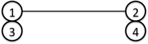
Nodes 1 and 2 for translational DOF, nodes 3 and 4 for rotational DOF.
(Triangular Shell Element)
| Surface No. | Linear | Quadratic |
|---|---|---|
| 1 | 1 - 2 - 3 [front] | 1 - 6 - 2 - 4 - 3 - 5 [front] |
| 2 | 3 - 2 - 1 [back] | 3 - 4 - 2 - 6 - 1 - 5 [back] |
(Triangular Shell Element with 3-dof nodes)
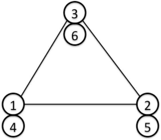
Node 1, 2 and 3 for translational DOF, nodes 4, 5 and 6 for rotational DOF.
| Surface No. | Linear |
|---|---|
| 1 | 1 - 2 - 3 [front] |
| 2 | 3 - 2 - 1 [back] |
(Quadrilateral Shell Element)
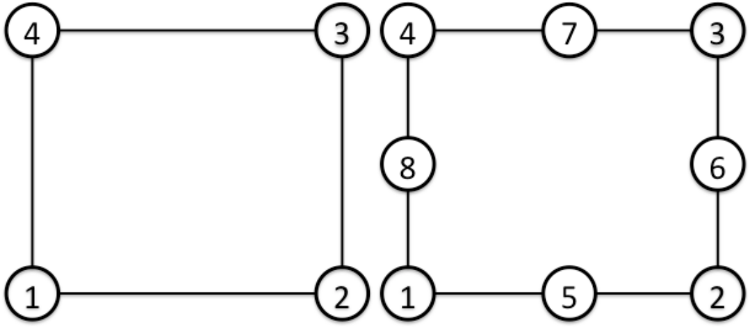
| Surface No. | Linear | Quadratic |
|---|---|---|
| 1 | 1 - 2 - 3 - 4 [front] | 1 - 5 - 2 - 6 - 3 - 7 - 4 - 8 [front] |
| 2 | 4 - 3 - 2 - 1 [back] | 4 - 7 - 3 - 6 - 2 - 5 - 1 - 8 [back] |
(Quadrilateral shell Element with 3-dof nodes)
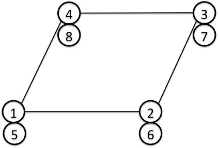
Nodes 1, 2, 3 and 4 for translational DOF, nodes 5, 6, 7 and 8 for rotational DOF.
| Surface No. | Linear |
|---|---|
| 1 | 1 - 2 - 3 - 4 [front] |
| 2 | 4 - 3 - 2 - 1 [back] |
Figure 4.1.2: Connectivity and Surface Number